What is laser marking?
Laser marking is a high-quality, efficient and fast method for robust and permanent markings
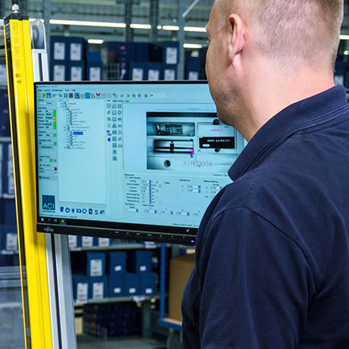
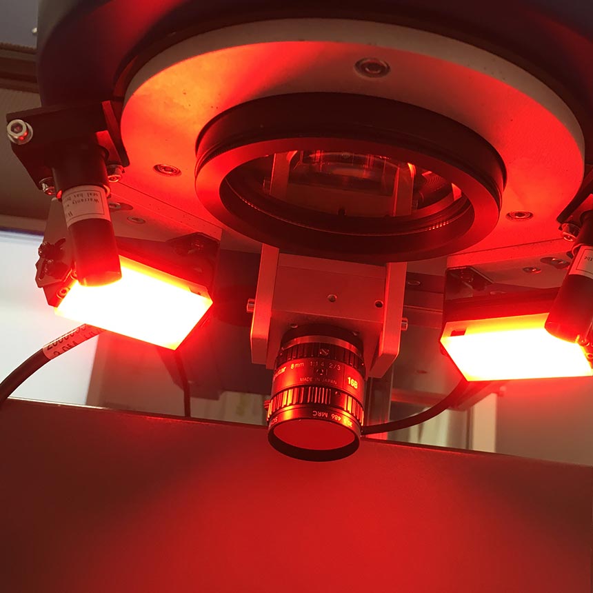
CPM (Capturing-Positioning-Marking) is a vision system for camera-based positioning of laser markings. It provides an accurate live or still image of the marking area and enables direct visual alignment of the layout on the actual component. The system is fully integrated into the ACI Magic Mark marking software – no additional software or interfaces are required.
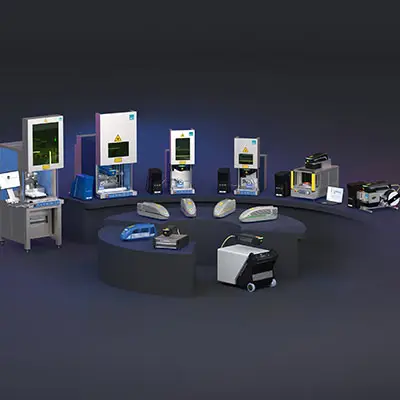
CPM Vision Systems at a Glance
The CPM Vision system from ACI Laser is available as an internal and external CPM. Both versions are used for camera-assisted positioning of markings on components and workpieces. The most suitable solution depends on the component size, desired image size, resolution requirements, and the laser system used.
With internal CPM, the camera is directly coupled into the beam path and looks over the scanner mirrors. This compensates for the thermal drift of the scanner, enabling particularly precise positioning.
Typical for internal CPM:
Camera in the beam path (scanner-based)
Very high resolution with small image sizes
Image size (single image): 5 × 5 to 13 × 13 mm²
Image size (composite image): 35 × 35 to 70 × 70 mm²
Resolution: 6 to 15 µm/pixel
The external CPM uses a camera to capture a live or still image of the marking area. The camera image is used in the Magic Mark laser software for manual positioning of the marking layout and is displayed with perspective correction.
Typical features of the external CPM:
Capture of large marking areas (depending on optics)
Flexible image sizes, even for larger components
Image sizes: 60 × 60 up to 160 × 160 mm², also user-defined
Resolution: 65 up to 200 µm/pixel
Integrated or external camera, depending on the laser system
| Live image of the marking area – enables visual inspection prior to processing | |
| Intuitive layout placement in the camera image – simplifies alignment and saves time | |
| Stitching for high-resolution details – ideal for fine structures and small marking areas | |
| Visual inspection before marking – prevents misalignment and rejects | |
| Fully integrated into Magic Mark – central control without external software | |
| Flexible adaptation to lenses, lighting, and resolution – for maximum compatibility |
sehr gut
gut
ungeeignet
| Internal CPM | External CPM | |
|---|---|---|
| Image sizes (single image) | 5 × 5 up to 13 × 13 mm² | 60 × 60 up to 160 × 160 mm² |
| Image sizes (composite) | 35 × 35 up to 70 × 70 mm² | |
| Resolution | 6 up to 15 µm/Pixel | 65 up to 200 µm/Pixel |
| Build form | Integrated in the beam path | Camera integrated or external, depending on the laser system |
| Typical parts | Small parts, high precision | Larger parts, flexible layouts |
| Compatible laser systems | Fiber lasers only | Fiber lasers, diode series lasers, CO₂ |
The CPM Vision system enables precise alignment of the marking layout directly on the camera image of the actual component. This makes it immediately apparent whether the marking is positioned correctly. CPM provides greater reliability and prevents misalignment, especially with small, complex, or frequently changing objects. This significantly reduces the error rate, minimizes scrap and rework, and increases process reliability in series production. Companies benefit from more stable processes and lower production costs.
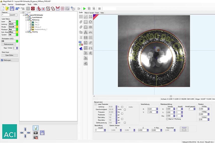
Depending on requirements, CPM displays a live image or a single image in the Magic Mark graphics area. The camera image is automatically distorted, perspective-corrected, and adjusted to the marking area. This ensures that the virtual marking and the actual object surface match exactly – the marking appears precisely at the intended position. This allows the alignment to be visually checked before processing, which prevents misalignment and significantly increases accuracy in the process.
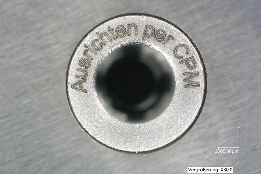
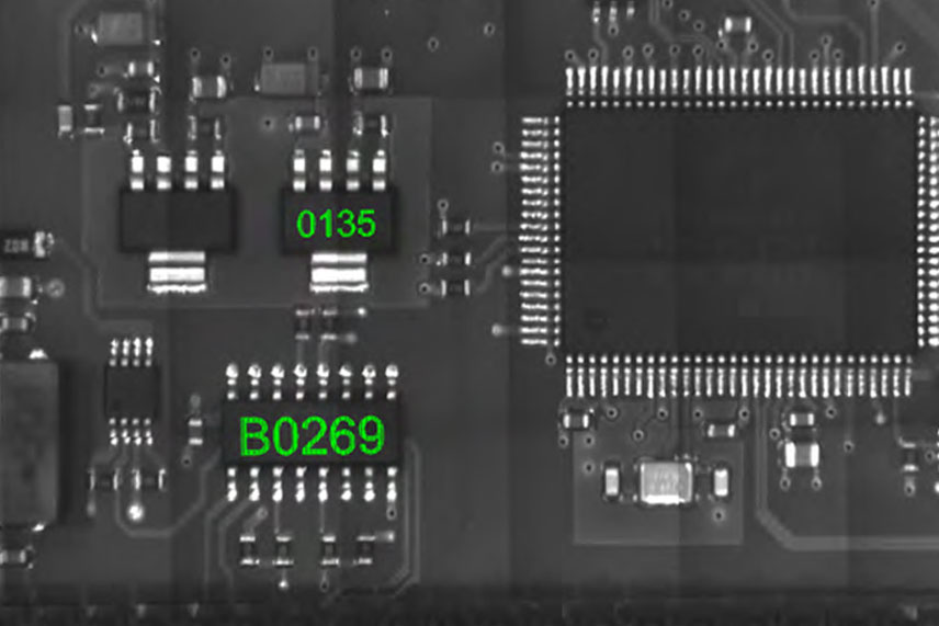
Stitching creates a high-resolution image of the marking area. This allows even the smallest marking areas, filigree structures, or details that are difficult to recognize to be accurately captured and aligned. Particularly in industries with high quality requirements – such as electronics manufacturing, medical technology, or trimming applications – the CPM Vision system helps to precisely position even the finest structures and mark, trim, or align them in a controlled manner.
The CPM Vision system is fully integrated into the ACI Magic Mark marking software. Positioning is done directly in the camera image – visually, intuitively, and precisely. Camera, lens, and lighting settings can be customized individually, allowing CPM to adapt flexibly to different components and production environments. Integration with Magic Mark also means that all process steps are controlled centrally – from visualization and alignment to marking. This keeps operation simple, safe, and efficient.
The CPM Vision System is used for camera-assisted positioning of laser markings. It displays the marking area as a live or single image and enables precise placement of the layout directly on the camera image or component. This allows markings to be visually checked and precisely aligned before the laser process starts.
The main differences lie in camera integration, image size, and resolution. The internal CPM is integrated into the beam path and offers maximum precision for small image sizes. The external CPM captures larger marking areas directly via the optics and is particularly suitable for larger components and flexible applications.
An internal CPM is particularly suitable when small components need to be positioned with very high accuracy. The integration of the camera in the beam path compensates for the thermal drift of the scanner, enabling particularly precise marking positioning. This requires the use of a fiber laser from the Business Fiber or Economy Fiber series.
The internal CPM is only available for fiber lasers, specifically for the DFL Ventus Marker from the Business Fiber and Economy Fiber series. The external CPM is available for diode lasers and CO₂ lasers.
The achievable image sizes and resolutions depend on the CPM variant.
With the internal CPM, the image sizes range from 5 × 5 up to 13 × 13 mm² (single image) or 35 × 35 up to 70 × 70 mm² (composite image) with a resolution of 6 up to 15 µm/pixel.
The external CPM achieves image sizes of 60 × 60 up to 160 × 160 mm² with resolutions of 65 up to 200 µm/pixel, depending on the optics and image size.
Without camera support, the positioning of the marking layout often has to be done manually and by eye. The use of a CPM Vision System reduces this source of error by supporting the user with a perspective-corrected live image. This significantly reduces the risk of incorrect markings, while increasing precision and process reliability.
No, the CPM Vision system does not require any additional software. It is fully integrated into the ACI Magic Mark marking software, so operation and positioning can be carried out directly in the familiar interface. However, it should be noted that CPM is a separate hardware module (camera unit) that must be present on the laser head or retrofitted. Camera-assisted positioning is only possible through the combination of hardware and Magic Mark.
Yes, the CPM Vision system can be retrofitted in many existing ACI laser stations. This makes it possible to equip existing systems with camera-based positioning and thus benefit from higher precision and process reliability—without having to purchase a completely new laser station.
The live image shows the entire marking area and allows the layout to be placed directly on the actual component. If required, a single image can also be used, which is automatically corrected and adapted to the marking area. This ensures that the virtual marking and the actual surface match exactly.
Stitching involves combining several individual images to form a single high-resolution image. This is particularly useful for small structures or delicate markings that would not be fully visible in the live image. Stitching provides the user with a detailed representation for maximum precision.
Press ENTER to confirm or press ESC to close